How to perform welding current adjustment
To date, the current adjustment of the welding machine can be performed by various methods. However, the most commonly used method is to adjust the current using the ballast resistance provided at the output of the re-winding. This method is not only reliable and simple to implement, but also effective, since in this way it is possible to improve the external characteristic of the transformer apparatus and increase the steepness of the fall. In exceptional cases, such resistances are used only to correct the rigid characteristics of the device for welding.

The welding machine is one of the most necessary devices in the home workshop.
Elements that will be needed for the manufacture of a current controller for a welding machine:
- cord;
- steel spring;
- nichrome wire;
- resistors;
- switch;
- coil;
- Scheme of current control of welding machine.
Using ballast resistance as a current regulator

Current control circuit.
The magnitude of the ballast resistance for the welding current controller is approximately 0.001 ohms. This value is most often chosen experimentally. To obtain ballast resistance, high-power wire resistances are often used, which are used in lifting devices and trolley buses. Also, these elements are used to cut the spirals of heating elements and high-resistance wire elements of large thickness. You can reduce the current even with a stretched steel spring for the door. Such resistance can be switched on permanently or in such a way that in the future it is possible to regulate the welding current relatively easily. One end of this resistance should be connected to the output of the transformer structure, the other end of the welding wire should be equipped with separate clamping devices that can spread along the length of the resistance spiral to select the required current.
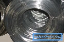
You can use nichrome wire with a diameter of 4 mm and a length of 8 m as a ballast. The wire may have a small diameter, in which case the length must also be appropriate. However, the smaller the length, the more the wire heats up. Be sure to take this into account.

As the ballast resistance, you can use nichrome wire.
Most of the high-power wire resistors are made in the form of open spirals that are mounted on a frame up to 0.5 m long. In such cases, the heating elements are also wound into a spiral. If a resistor element made of magnetic alloys is combined with a spiral or with some elements of steel, the spiral will vibrate excessively during the passage of significant currents. It should be understood that the spiral is the same solenoid, and significant welding currents create high-power magnetic fields. It is possible to reduce the effect of vibrations by stretching the spiral and fixing it on a solid base.
The wire can be bent and snake to reduce the size of the manufactured resistor element. The cross section of the material of the resistor that conducts current, you need to choose a large, because in the process of the equipment will be very hot. A wire of insufficient thickness will become very hot, however, it can be used quite effectively to adjust the current of the welding machine. It should be understood that in the process of heating the properties of the material can change greatly, because it is difficult to judge the resistance value of such a wire resistor.
Back to table of contentsUsing reactance to adjust current

The main parts of the welding machine.
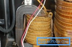
In industrial welding devices, the adjustment of current through the use of active resistances is not popular due to the bulkiness and overheating of the elements used. However, reactance is often used — the use of a choke in the secondary chain. Chokes can have a different design. Often they are combined with the magnetic wire of the transformer structure as a whole. However, they are made so that their inductance and resistance can be adjusted by moving the elements of the magnetic wire. In this case, the choke will also improve the process of burning the arc.
Adjusting the current in the secondary chain of the transformer structure for welding poses some problems. Through the device for adjustment will pass significant currents, which can lead to bulkiness. Another disadvantage is switching. For a secondary chain, it is rather difficult to select common switches of suitable power that can withstand current up to 200 A. In the initial winding chain, the currents are approximately 5 times less, therefore it is quite easy for them to choose switches. Ballast resistances can be switched in series with the initial winding. However, in this case, the resistance of the resistor elements should be much greater than in the re-winding chain.

As a power source for the welding machine, special batteries are used.
You should be aware that a battery of 8 ohms from several devices of the FEV-50 100, which are connected to each other in parallel, will be able to reduce the output current by 2-3 times. In this case, everything will depend on the transformer structure. You can prepare several batteries and mount the switch. If there is no high power switching element available, then several switches can be used.
In the process of turning on the ballast resistance in the initial chain, the benefit will be lost, which will give resistance in the secondary chain. Improvement of the falling parameter of the transformer structure will not occur. However, the resistors, which are connected to high voltage, will not lead to negative consequences in burning the arc. If the transformer structure is well welded without them, then it will cook with additional resistance in the initial winding.
When working at idle, a transformer device consumes a small current, hence its winding has significant resistance. Therefore, 2-5 ohms will not affect the output voltage of the idle.
Back to table of contentsInstall a choke to adjust current

Scheme of the welding machine.
Instead of resistor elements that can overheat during operation, a reactant - choke can be mounted in the initial winding chain. This scheme can be used only if there are no other devices to reduce power. The inclusion of such resistance in the high-voltage chain will greatly reduce the no-load voltage of the transformer structure. A voltage drop occurs in control devices with a relatively high no-load current of 2-4 A. In the case of a small use of the current, no voltage drop will occur. The choke, which is included in the initial winding of the transformer device, will lead to a slight deterioration in the welding parameters of the transformer structure, but it can still be used. In this case, everything will depend on the properties of the used transformer device. On some welding devices, embedding the choke in the main chain of the transformer structure will not affect.
As a device choke, in order to regulate the current, you can apply the re-winding of the existing transformer structure, which is calculated on an output of about 40 V. The power of the device should be approximately 250-300 watts. In this case, you will not need to change anything. However, it is recommended to make a choke independently. To do this, you need to wind the cord on the frame of the transformer structure with a capacity of 250-300 watts. Every 50-60 turns, you need to make taps that are connected to the main switch. For the manufacture of choke fit element from the TV.
Back to table of contentsHow to make a choke with your own hands?

A choke can replace resistor elements.
The choke can be made by yourself and on a straight core. This is true if there is a straight coil with a large number of turns of a suitable cord. Inside the coil will have to push a package of straight plates of iron from the transformer. The desired reactance can be set by selecting the thickness of the package. Need to navigate the welding transformer device.
Design example: a choke, which is made of a coil with 400 turns of a cord with a diameter of 1.4 mm, is packed with an iron package with a cross section of 4.5 cm². The length of the wire is equal to the length of the coil. In this case, the current of the transformer device 120 A can be reduced by 50%. Such a choke can be made with adjustable resistance. To do this, you will need to change the depth of the core core entering the coil. Without this element, the coil has a small resistance, however, in the case of complete introduction of the rod into it, the resistance will be maximum. A choke that is wound with a suitable cord will practically not heat up, but the core will vibrate violently. This point must be taken into account in the process of screeding and fixing a set of iron plates.

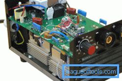
If you carefully remove the case from the welding machine, you can see its main details.
For self-made devices in the process of winding windings, it is necessary to make taps and change the number of turns. So you can control the current. However, this method can be used exclusively for adjusting the current; it cannot be adjusted over a wide range. To reduce the current by a factor of 2-3, it will be necessary to greatly increase the number of turns of the initial winding. As a result, there will be a decrease in voltage in the secondary chain. You can increase the turns of the coils, but this will lead to an increase in the consumption of the cord, the size and weight of the transformer structure.
To perform a more accurate adjustment of the current in the lower side, you will need to use the inductance of the welding cable.
The cord must be laid rings. However, do not get carried away, as the cord will be very hot.
Back to table of contentsUsing a thyristor and triac circuit
Recently, thyristor and triac current control circuits have been used. In the process of applying to the output to control a voltage element of a specific value, the stabilizer will open and quickly pass a current through itself. In the current control circuit, which operates from a variable voltage, the pulses for control most often arrive at half of each period. The regulator will open at specific points in time, as a result, the beginning of each half-cycle of a sinusoidal current will be cut off and the total power of a suitable signal of electricity will decrease.

During the work with the welding machine it is necessary to observe security measures.
The current and voltage in this case will not have a sinusoid shape. Such a regulator circuit allows power adjustment in a wide range. A person who understands electronics will be able to make such schemes. When using regulators of this type, the arc burning process may deteriorate. In the case of a decrease in power, the arc will burn in separate flashes. In most of the thyristor devices, there are non-linear scales, the calibration will change along with the change in the mains voltage. The current will gradually increase in the process of work due to the fact that the heated circuit elements. Most often, the output power is greatly reduced, even in the case of the maximum position of the regulator. You should be aware that transformer devices are extremely sensitive to this. This method of adjusting the welding current is not popular because it is unreliable, and it is very difficult to implement it.
To measure a large current, it is necessary to prepare a clamp meter. The strength of the current can be measured at a distance, without having to touch it. The device has a divider circuit, which will cover the cable with current. The electric magnetic field of a current that flows in a given cord will induce a current in a closed loop. It can be measured.
It is easy to make a current regulator with your own hands, you just need to know the manufacturing technology and take into account all existing nuances.