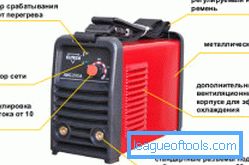
How to make a welding machine with your own hands
Before you decide how to make a welding machine with your own hands, a scheme is prepared. A transformer with three phases and a power of 1-2 kW, a pipe, a cable, a wire is used for its manufacture.

The circuit design of the transformer welding machine.
Preparatory work
Pre-removed secondary winding. The middle winding is rewound with a wire in steps of 30 turns. For self-production of the welding machine will require 25 m of cable. Such work is done with the help of extra hands. The terminals can be made of copper tube, whose diameter is 10 mm. On the other side of the wire cleaned. Remove screws and nuts from the panel. Fasteners are replaced with new analogues with M10 threads.

The electrical circuit of the bridge rectifier welding machine.
To withdraw the primary winding, you will need to make an additional fee. Textolite with a thickness of 3 mm is used for this. The board is attached to the transformer. Pre-make 10 holes with a diameter of 6 mm. M6 screws are inserted into them. If the welding machine is powered from the 220 V network, then the extreme windings are connected in parallel, and the middle ones are connected in series.
The device, which operates on 380 V mains, is manufactured by serial connection of the primary windings. To make an electric holder, you will need its scheme and a pipe with a length of 250 mm. With 2 ends of the product (indent 30-40 mm) make the notches. Wire is welded to the pipe with a diameter of 6 mm. A hose is put on the pipe. The device is connected to the network.
The primary current should not exceed 25 A, and the secondary 120 A. Experts recommend turning off the self-made welding machine after using 10-15 electrodes. The transition from the 1st welding mode to another provides for the shutdown of the network switch. If the cross section of the wire is insufficient, then winding is done in 2-3 wires. If the scheme of the unit involves the use of aluminum wire, then its cross section is increased 1.6 times.
Back to table of contentsCorrect winding

Scheme device inverter welding machine.
When self-fabricating a welding machine, special attention is paid to winding. It should be made in one direction. All layers of the winding are insulated with fiberglass. A cotton cambre is put on the conclusions. If poor quality wire insulation is observed, then the winding is done in 2 cables. The next row is wound after reliable fixation of the previous layer.
Network winding is located in 2 ways:
- using 2 windings, which are located on different sides of the core;
- using wire and core.
The next stage involves checking the apparatus for the presence of short-circuited turns. The transformer is connected to the network using a fuse or ammeter. If the 1st unit fails, then there is a short-circuited turn in the primary winding. The primary winding is rewound with regard to quality insulation.
The hum, issued when the device is in operation, indicates a low number of turns of the primary winding. The unit is considered to be operational if it consumes at idle less than 1 A. The secondary winding is wound from 2 sides of the core. If this process is performed using arcs, then a wire with a cross section of 15-20 mm is required. Winding on the free side of the core more than 60% of turns is allowed. The rest of the winding is wound on the primary analogue. To switch the operating mode of the unit, you will need a copper tip and terminals. The first elements are made of a pipe with a length of 30 mm. During operation it is recommended to set the switch to the neutral position.
Back to table of contentsSelf tuning

The design of the welding inverter.
Welding using a homemade machine is performed when the current and voltage values are in the desired range. At low welding current, it is required to redistribute the turns of the secondary winding in the direction of increasing the number of turns that are wound on the network analog. A device for measuring voltage is connected to the output winding of the device. The adjustment is carried out by a tester (for independent control of the welding output voltage).
To get the exact value, you need to remove 3 points. It is more difficult to adjust the current meter, as it is connected to the transformer, made by hand. The last device is presented in the form of a toroidal core with 2 windings. Its external diameter must be 40 mm. The core is made of transformer steel or ferrite. For the other winding is characteristic 600 turns. It connects to a current meter.
The next step involves setting up a current meter. For this, a calibrated resistance is connected to the winding for 2 seconds. The strength of the current is determined by Ohm’s law.
If welding works are performed in different conditions, then the device is tuned to the optimum mode.
Then the switch is set to the neutral position. Independent manufacture and adjustment of the apparatus for welding is carried out with proper experience in electricity.