What can be welding inverter circuit
All schemes of welding inverters consist of power and control parts.

Device of the invertor welding machine.
Today, inverter-type welding machines are popular. Popularity is associated with their low cost. Designs have a large number of advantages, but from time to time they, like other devices, need to be repaired. In order to repair an inverter, you will need to know its device and main functional units.
The design itself for welding is a high power power unit. The principle of its operation is similar to pulsed power supply units, which include, for example, power supply units for AT and ATX computers. The similarities lie in the way energy is converted.
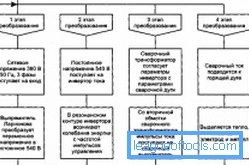
The energy in the welding device is converted as follows:
- AC voltage of 220 V is rectified.
- Converts a continuous voltage to an alternating high frequency.
- Intensity decreases with high frequency.
- Undervoltage straightens.

Current conversion in welding inverter
Previously, a high power power transformer was used as the main component of the welding inverter. It reduces the temporary voltage of the electrical network, with the result that you can get from the re-winding large currents (10-100 A), which will be needed for welding. If the intensity is reduced at the rewinding of the transformer structure, it will be possible to increase many times the current that the rewinding can give to the load. As a result, the number of turns of the rewinding will be reduced, and the diameter of the wire for the winding will grow.
Transformer structures are more powerful. They operate at a frequency of 50 Hz, have large dimensions and weight.
In order to eliminate this drawback, inverter devices for welding are being developed. In these devices, the working range is increased to 65-80 kHz, as a result of which the dimensions and the total weight of the structure are reduced. The working frequency of the conversion is increased by 4 times, which reduces the size by about 2 times. As a result, the costs of copper and other materials for the construction of fixtures are reduced.
The frequency of the temporary current of the electrical network is only 50 Hz, so there may be a problem with the operating frequency of the device 65-80 kHz. To do this, use the welding inverter circuit, which includes high-power transistors. Such devices can be switched with a frequency of 65-80 kHz. In order for transistor products to work, it is necessary to apply continuous voltage to them, which can be obtained from a rectifier device.

Scheme of the transformer Inventor.
The intensity of the electrical network will be straightened by a high-power bridge and smoothed out by condenser products for filtration. As a result, a continuous voltage of more than 220 V will be obtained at the output of the rectifier and the filter. This is the initial stage of conversion.
This intensity will be used as a power source for the inverter circuit. Transistor products of the high power inverter are connected to the transformer structure for lowering. Transistor products are switched with a high frequency of 65-80 kHz, and therefore the transformer design will also work at this frequency. To operate at high frequencies, smaller transformer devices are needed. Therefore, the transformer will be compressed to small sizes, while its power remains unchanged.
There are some difficulties with the conversion, so there are other details in the welding inverter circuit that are intended for the device to work stably.
Welding inverter circuit and power block design
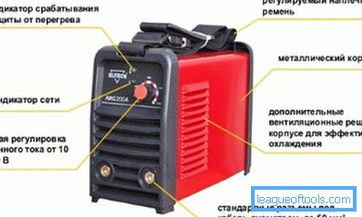
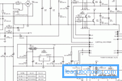
The appearance of the welding board with an indication of the placement of the main components of the scheme can be seen in fig. 1. First of all, you should understand the circuit of the power unit, which can be seen in fig. 2

Figure 1. Scheme of the welding plate.
The welding inverter circuit consists of the following components:
- noise filter;
- slow start relay;
- capacitor elements;
- network rectifier;
- current sensor;
- cooler;
- transformer construction for lowering;
- radiators.
Welding inverter mains rectifier
First of all, the alternating current of 220 V is rectified by a high-power bridge, after which it is filtered by electrolytic capacitor elements. This is necessary so that the temporary current of the electrical network with a frequency of 50 Hz becomes permanent. Capacitor elements C21 and C22 are needed in order to smooth out the ripple of the rectified voltage, which will always be after the diode rectifier element. The rectifier device is implemented according to the standard scheme of the diode bridge. It is performed on the assembly of PD1.
It should be noted that the intensity of the condenser elements of the filter will be almost 1.5 times greater than at the output of the bridge. Consequently, if after such a bridge 220 volts with pulsations are obtained, then 310 V continuous voltage will be obtained on the capacitor elements. In most cases, the operating voltage is limited to 250 V, since the intensity in the network is in some cases overestimated. Therefore, the output of the filter will be 350 V. As a result, the capacitor elements will have a voltage of 400 V, while there will be some reserve.

Figure 2. Scheme of the power part of the inventory.
On the printed circuit board of the welding device, the elements of the network rectifier element occupy a large amount of space. The diode bridge for rectification is mounted on the radiator structure for cooling. Huge currents will flow through this assembly, as a result of which the diodes heat up. To protect the bridge, a thermal fuse should be installed on the radiator device, which will open if the temperature of the radiator structure exceeds 90 ° C.
GBPC 3508 type assemblies are used in the rectifier. This assembly is calculated for a forward current of 35 A and a voltage of 800 V.
After the bridge, several electrolytic capacitor elements are installed, the capacity of each of which is 680 microfarads, and the working voltage is 400 V. The capacity of the capacitor devices will depend on the model of the device used. Continuous intensity from the rectifier and filter will be applied to the device.
Back to table of contentsInterference Filter and Inverter Device
In order to interfere with the high frequencies that will occur during the operation of the inverter for welding, could not get into the electrical network, before the rectifier product will need to install an electromagnetic compatibility filter. According to the scheme, such a filter consists of elements C1, C8, C15 and the throttle product on the ring wire T4.

Interference filter circuit.
The inverter device is assembled according to the scheme of an oblique bridge. In this case, several key high-power transistor products are used. As the main transistor devices can be used as IGBT-elements, and MOSFET. Such components will need to be installed on the radiator device so that heat can be removed.
Continuous intensity will be switched by transistor products Q5 and Q8 through the winding of the transformer structure T3 with a frequency much higher than the frequency of the electrical network. The switching frequency can be 10-50 kHz. In this case, a temporary current will be created, as in the electrical network, but it will have a frequency of 10-50 kHz.
In order to protect transistor products from unwanted intensity surges, RC chains should be used.
To reduce the intensity, a high-frequency transformer element T3 is provided in the circuit. Using transistor products Q5 and Q8, the initial winding of the transformer structure T3 will switch the intensity that can flow from the rectifier. The result is a continuous voltage of 310-350 V.
Thanks to transistor products, continuous intensity will be converted to temporary.
Transformer products cannot convert direct current.
With the rewinding in the transformer device T3, it will be possible to remove a much lower intensity (about 65-70 V). In this case, the maximum current will reach 125-130 A, therefore it is advisable to use a transformer device T3. Through the initial winding will flow a small current, but a large voltage. A small voltage can be removed from the rewinding, but the current in this case will be large.
Back to table of contentsScheme of the output rectifier welding inverter
This element is assembled on the basis of high-power single-cathode diodes.
The fixtures will rectify the temporary high frequency current. In the case of repair work, it is recommended to replace the diodes in the output element for straightening with the high-speed ones.
Each welding inverter has its own scheme, but the main elements are the same everywhere.